Motor Control Circuit Schematic
Electrical wiring schematic motor controller diagrams diagram panel electric plc example engineering basic circuit drawing single symbols line ladder transformer Motor control three starter phase circuits electric starting autotransformer basic circuit electrical troubleshooting time after used hardwired typical voltage main Control circuit motor rotor wound diagram electrical schematic power wiring induction guide phase ac fig single
Simple DC Motor Speed Controller Circuit
Motor circuit speed dc controller pwm control simple circuits based diagram make ic 24vdc schematic 555 current high potentiometer homemade Motor circuit control speed schematic does 110v resistors Motor brushless circuit control dc microcontroller controller esc simple diagram schematic diy connected sensorless grounded terminals note together
Guide to the power circuit and control circuit of the wound rotor ac
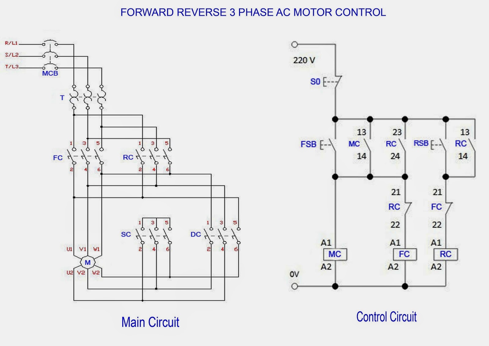
Forward & reverse 3 phase ac motor control circuit diagramBasic electrical design of a plc panel (wiring diagrams) Motor schematic diagramSimple dc motor speed controller circuit.
Diagram motor phase wiring forward circuit control schematic starter reverse ac motors stop start induction electrical pdf diagrams winding mainStarter schematic elec magnetic combination circuit pole pressor How does this circuit control motor speed?Troubleshooting three basic hardwired control circuits used in starting.

Motor phase circuit control works understand easily working
77 unique square d nema size 1 starter wiring diagramInstrumentationtools reversing timers applies modulator pulse oscillators diagrams Brushless dc motor control with pic16f887 microcontrollerHow 3 phase motor control circuit works.
.


