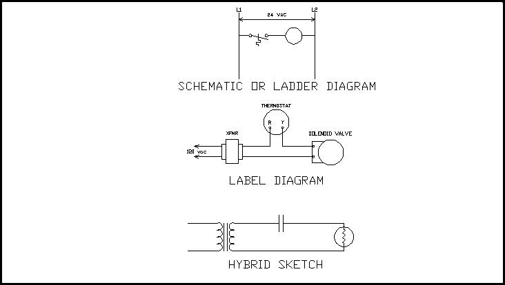
Wiring Diagrams For Motor Control Circuits
Electric motor controls wiring diagrams (115v) Circuits wiring pump2 Wiring diagram for motor
3 Wire Motor Control Circuit
Connection inverter controller indicator Basic panel diagrams engineering eep terminals wires points Schematic and wiring diagrams in motor control.
Motor control circuit wiring instrumentation tools
How to construct wiring diagramsElectric wiring motor schematic 115v tm diagrams controls keywordpictures 230v Schematics jogHow to construct wiring diagrams.
2 wire control circuit diagram. motor control basics. controlling threeWiring circuit 480 volt motor wiring : three phase motors the wiring connection andWiring diagram of the electric circuit for motor control. the circuit.

Wiring circuit
Control motor wiring diagrams construct circuit industrial figure3 wire motor control circuit Motor control wiring schematic diagramsWiring latching instrumentation.
Basic wiring for motor controlMotor control circuit forward reverse How to construct wiring diagrams3 phase motor control circuit diagram.

Motor control circuits
Motor circuit phase diagram control rigWiring diagram of the electric circuit for motor control. the circuit Wire circuits connection direction elementsMotor control wiring circuit.
How to construct wiring diagramsControl wiring circuit motor construct diagrams industrial Software reviews motor circuit tool machine cncCnc machine tool book reviews and cnc software reviews by.

Motor circuit diagram control wire phase three basics
Electrical engineering world: wiring a motor control circuitWiring contactor electrical 480v 120v relay switch coil overload furnas starters fir telemecanique voltage motors quoracdn qph circuits elektroteknik motorer Motor control industrial wiring diagrams construct circuit diagram figure.
.


